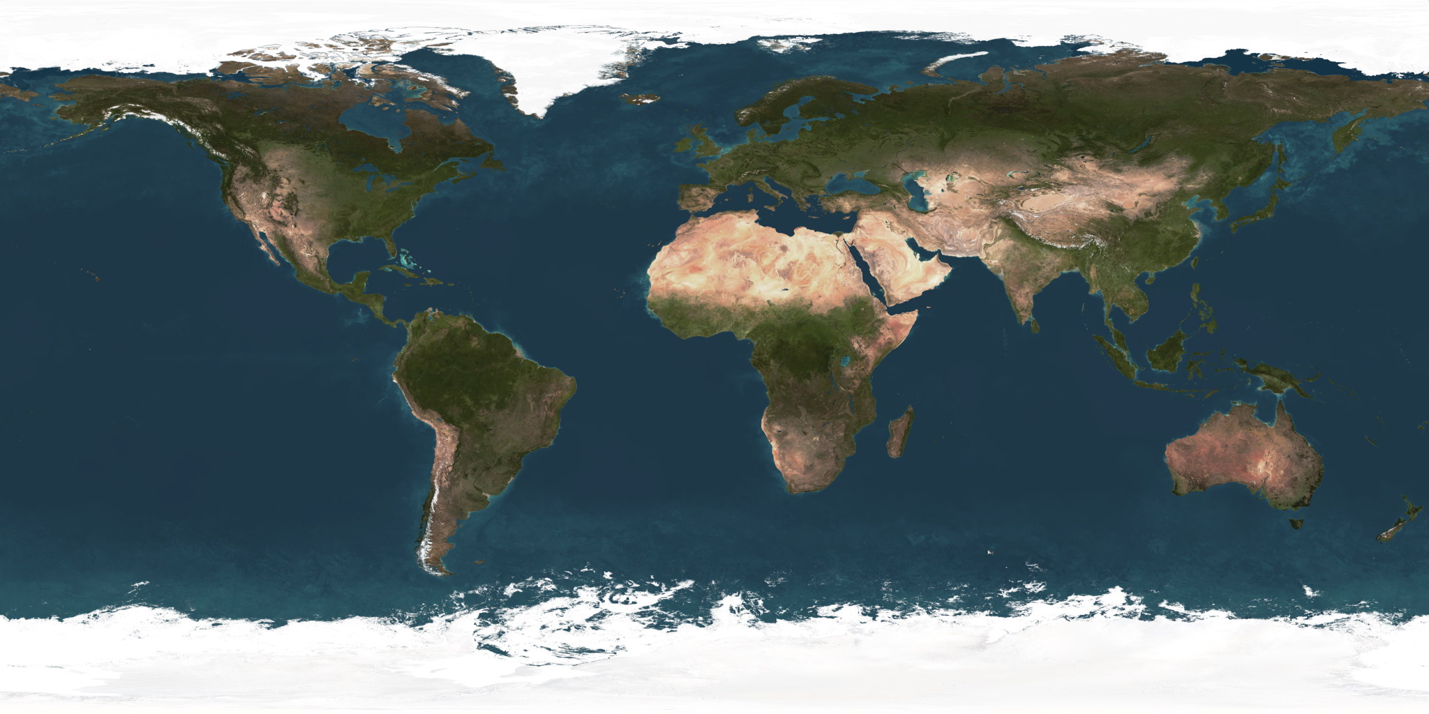
SPHERICAL COORDINATES
Firstly we need to calculate the spherical coordinates for each pixel in the output equirectangular image. If the coordinates in the equirectangular image are x and y; and the width & height of this image are w, h respectively then the normalised coordinates (u, v) ranging from 0 - 1 are given by:
				u = x / w

				v = y / h
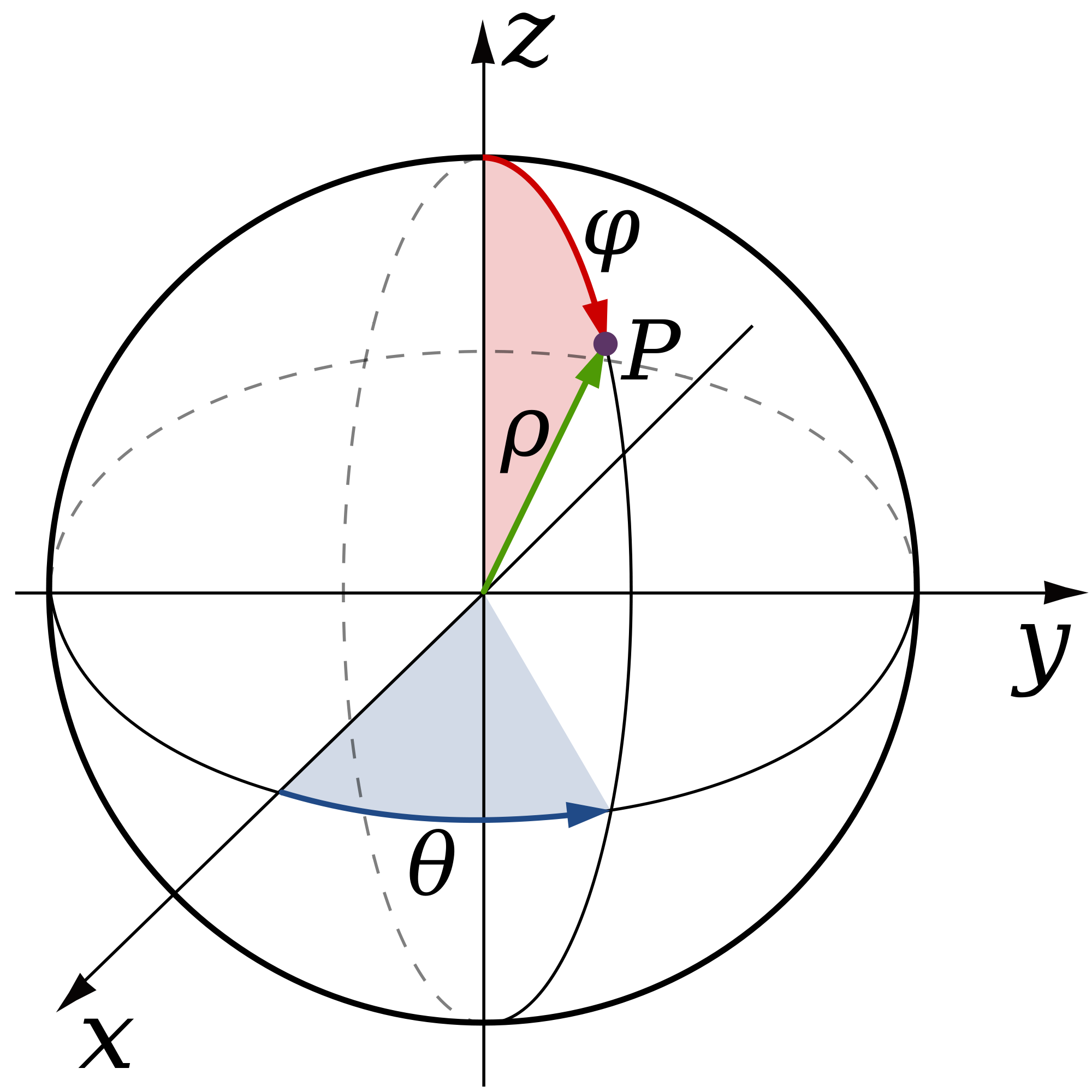
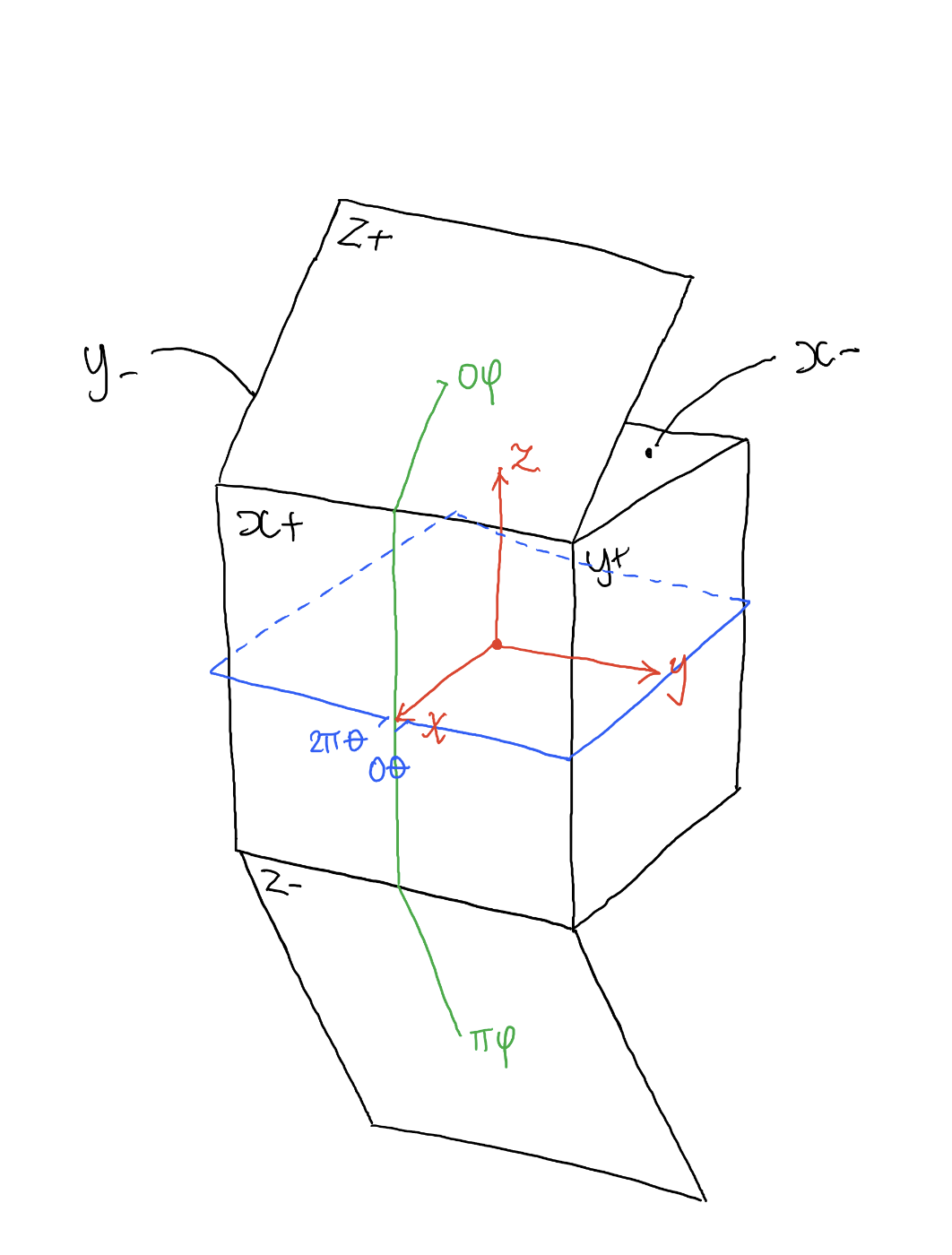
The spherical coordinates θ and φ are calculated from the normalised coordinates u, v. θ is defined to be
the angle in the xy plane from the X+ axis with 0 ≤ θ ≤ 2π. φ is defined to be the polar angle
from the positive Z axis with 0 ≤ φ ≤ π:
				θ = u*2π

				φ = v*π
CARTESIAN COORDINATES
Now we can use the 3D polar coordinates to form a unit vector and work out which face of the cube we're pointing towards. We can do this by using the following equations, note that 'r' has been removed as we're producing a unit vector (the distance in this this is one therefore there's no need to include this):
				x = cosθsinφ

				y = sinθsinφ

				z = cosφ
Next we find the maximum absolute value; then divide each of these coordinates by this value. This means either xx, yy or zz will equal positive or negative one. Whichever of these does is the largest value, and the sign will indicate whether it's positive or negative. So, for example if 'xx' equals +1 then it means that the ray is mainly pointing towards the positive x face:
				maximum = max(abs(X),abs(Y),abs(Z))

				xx = x / maximum

				yy = y / maximum

				zz = z / maximum
As demonstrated in the image below:
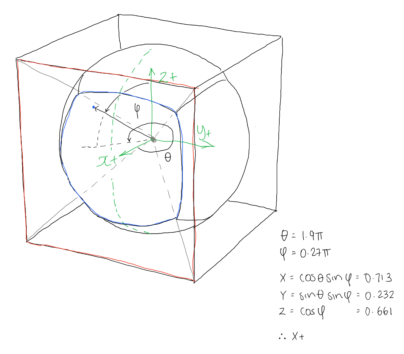
So for example in the image above we can we can see that xx = 0.713, yy = -0.232 and zz = 0.661. The maximum absolute value of this is 0.713, for x. And it's positive so we know the face this ray is mainly pointing towards is the X+ face.
3D PROJECTION
By this point we know which direction the ray is pointing in and which cube face it will hit. Knowing this information allows us to calculate the distance from the centre of the sphere to the point where it intersects with the cube map.
				if(xx==1 or xx==-1):

				    projectX(theta,phi,xx)

				else if (yy==1 or yy==-1):

				    projectY(theta,phi,yy)

				else:

				    projectZ(theta,phi,zz)
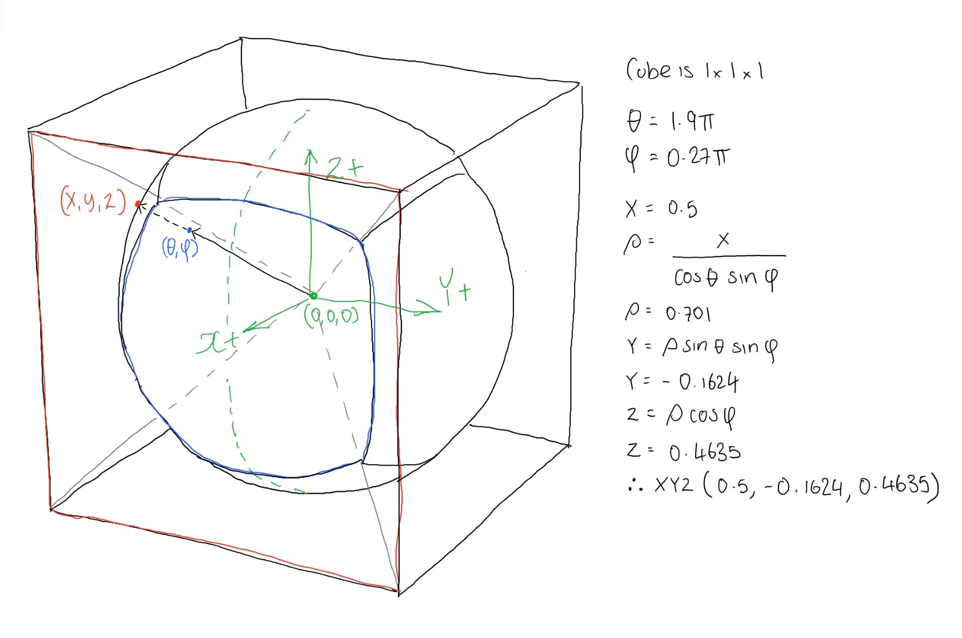
So we now know which face we're pointing towards. We can use this information to help work out the coordinates for where the ray hits the cube face. If for example we're selecting the X+ face we know the coordinate where the ray intersects the cube will at least have an X coordinate that matches half the length of one of the cube map lengths. In my code I just assume a cube of size 1x1x1 centred on (0,0,0). Therefore the X coordinate in this case will be 0.5:
				def projectX(theta,phi,sign):


				    x = sign*0.5

				    rho = x/(cos(theta)*sin(phi))

				    y = rho*sin(theta)*sin(phi)

				    z = rho*cos(phi)

				    return (x,y,z)
As you can see demonstrated below:
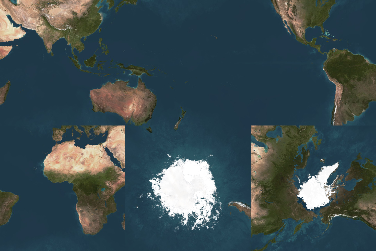
2D CUBEMAP PIXEL
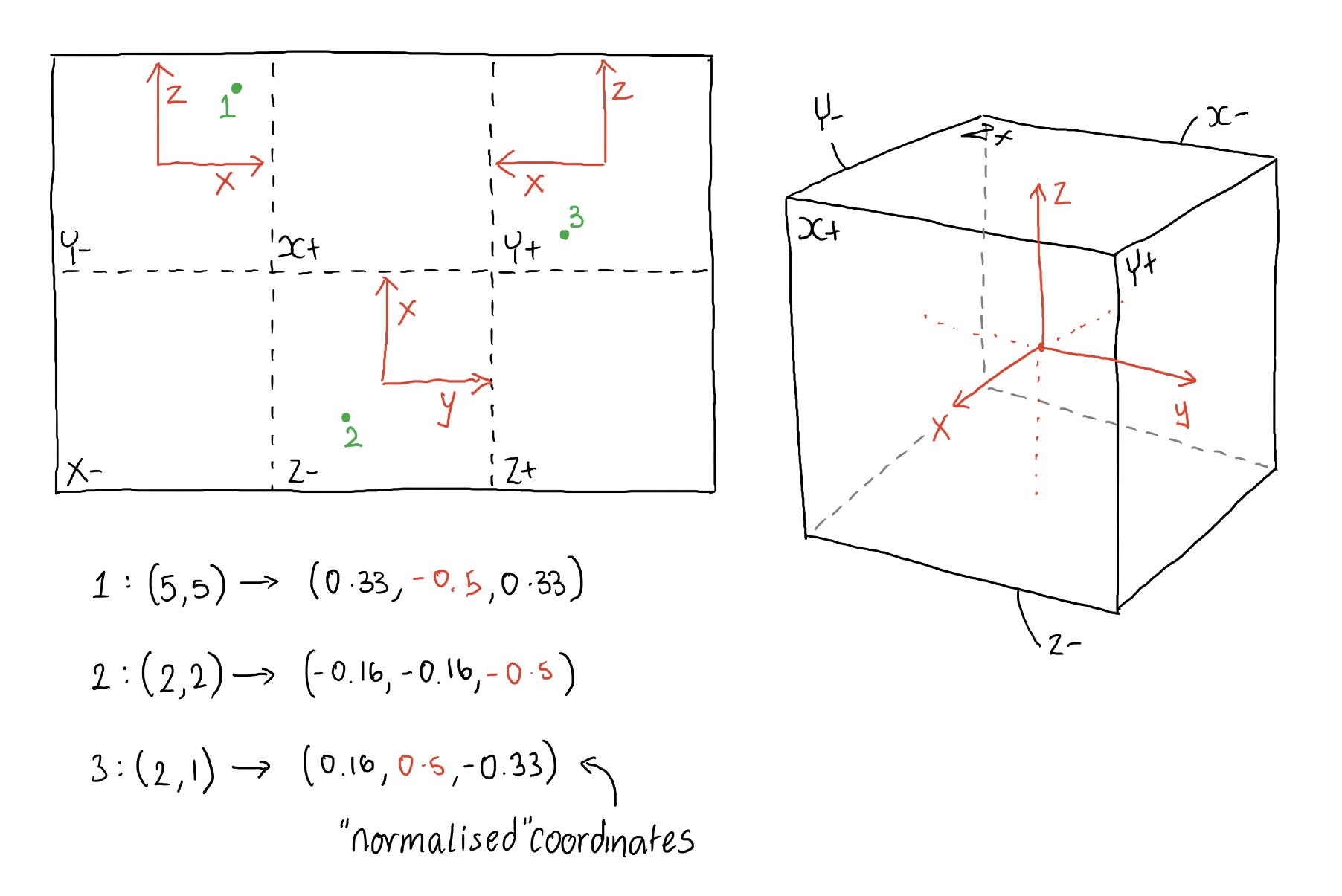
Now we have the coordinate of where we need to extract a colour from the cube map. Currently this coordinate is 3D and is located somewhere on a cube which has dimensions 1 x 1 x 1. Now, we know that the cube is broken down into the following faces (shown slightly unfolded):
We know it's broken down like this for a number of reasons:
- We know θ is in the XY plane, from the positive X axis and has a total range of 2π radians. This means the X+ face is split in two, less than 0.25π & greater than 1.75*π
- We know that for equirectangular images as we increase θ we travel from X+, Y+, X- and so on, anti-clockwise.
- When φ = 0 we're pointing towards the top of the cube, therefore at the Z+ face, when φ is π it is pointing directly downwards at the Z- face.
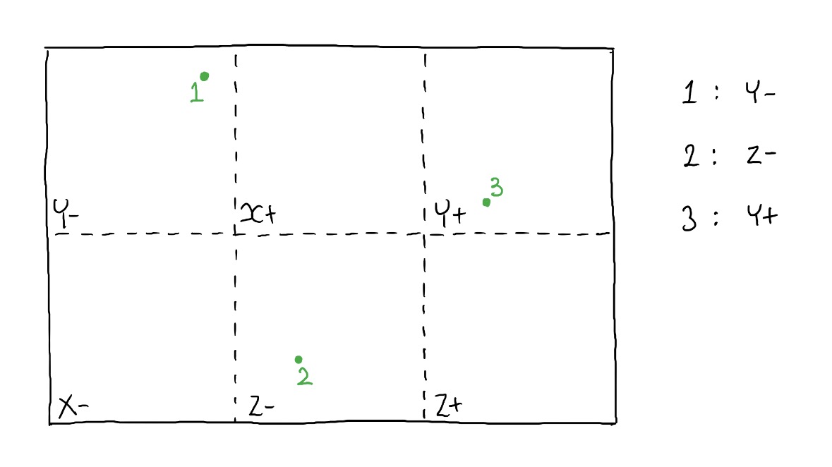
We need to convert the 3D coordinates to a 2D coordinate. As you can see in the images above and below you can see this isn't a simple case:
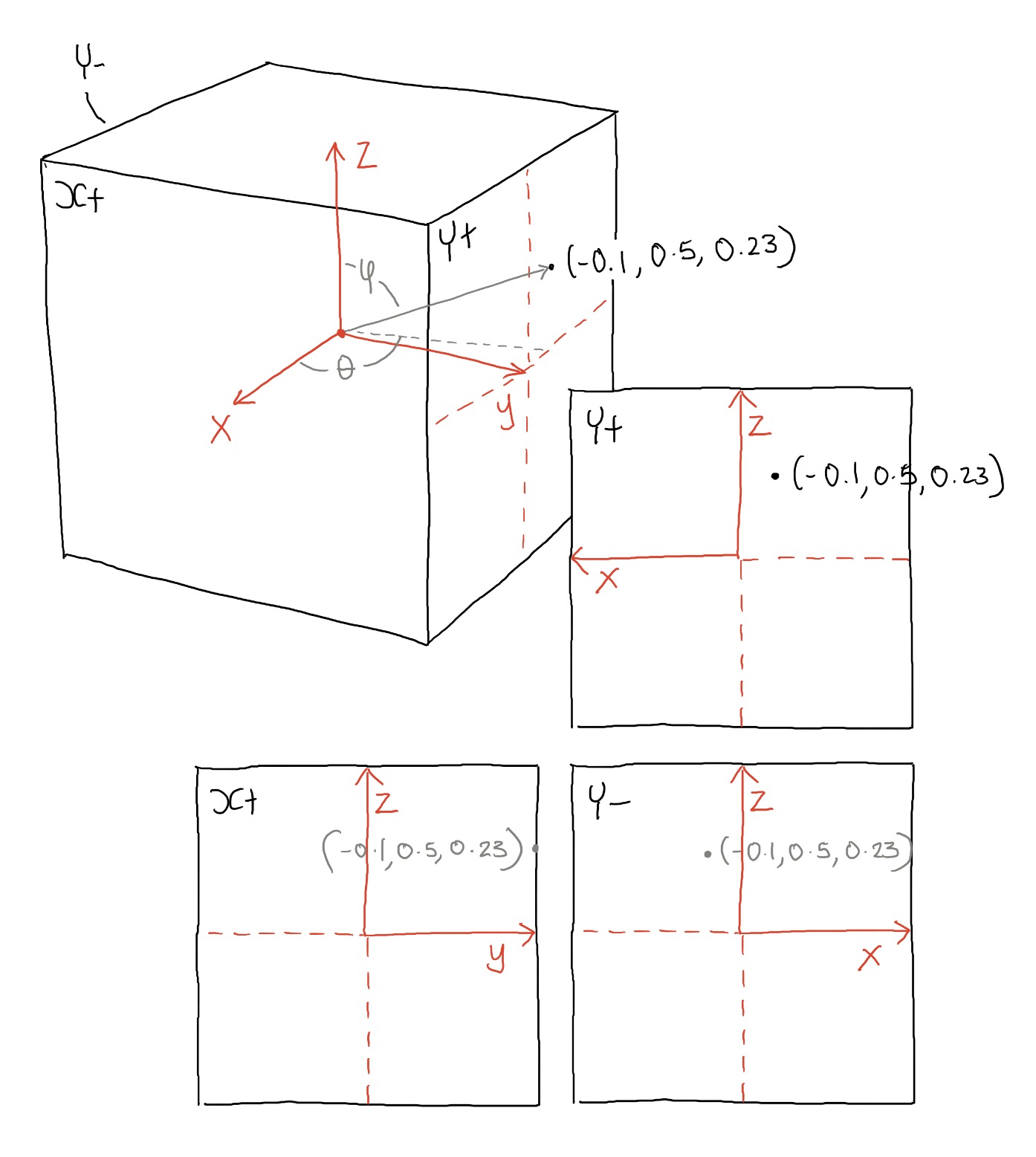
Depending on which face you're on, the axis orientation swaps around as you can see above. On the positive Y face, the X axis points to the right, in Y- it points to the left. We need to change this for each of the faces so that the bottom left corner is xy (0,0) and the top left is (1,1) - as you can see this will be slightly different for each face.
This is quite a simple process to convert between the two coordinates using the code below:
				def unit3DToUnit2D(x,y,z,faceIndex):


				    if(faceIndex=="X+"):

				        x2D = y+0.5

				        y2D = z+0.5

				    elif(faceIndex=="Y+"):

				        x2D = (x*-1)+0.5

				        y2D = z+0.5

				    elif(faceIndex=="X-"):

				        x2D = (y*-1)+0.5

				        y2D = z+0.5

				    elif(faceIndex=="Y-"):

				        x2D = x+0.5

				        y2D = z+0.5

				    elif(faceIndex=="Z+"):

				        x2D = y+0.5

				        y2D = (x*-1)+0.5

				    else:

				        x2D = y+0.5

				        y2D = x+0.5


				    y2D = 1-y2D
Notice that at the end I change the orientation of the Y axis - this is due to the fact I'm using python and the y axis is flipped so that (0,0) is the top left corner of the image.
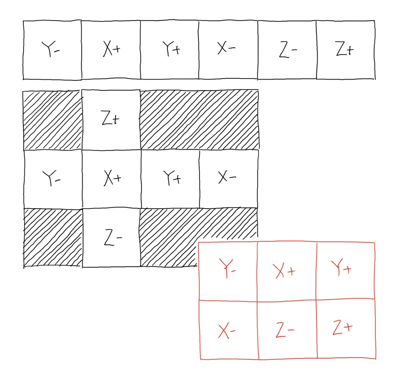
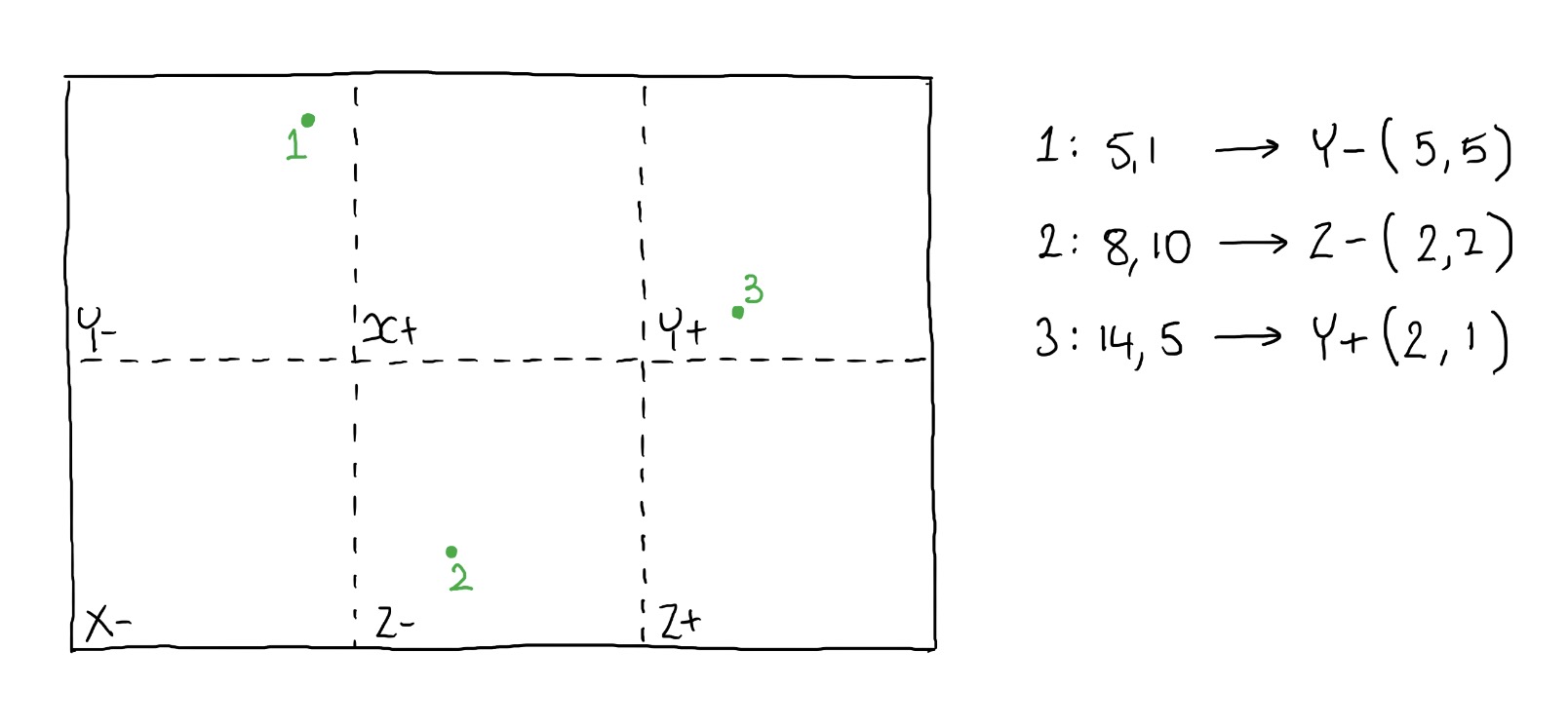
So at this stage we know what face we're looking at, and what pixel within that face. There is now just one final step in the process and that is to work out where the faces are located within the input image. This is a very simple process, but varies according to what input images you have, and what layout they take. So your cube map may be set up as a cross, or a rectangular series of images such as demonstrated below:
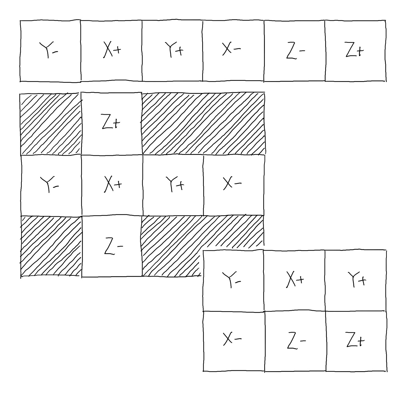
I use a simple function to shift the face coordinates to the correct location in the cube map:
				def offset(x,y,face):


				    if(face=="X+"):

				        ox = 1

				        oy = 0

				    elif(face=="X-"):

				        ox = 3

				        oy = 0

				    elif(face=="Y+"):

				        ox = 2

				        oy = 0

				    elif(face=="Y-"):

				        ox = 0

				        oy = 0

				    elif(face=="Z+"):

				        ox = 5

				        oy = 0

				    elif(face=="Z-"):

				        ox = 4

				        oy = 0


				    ox *= squareLength

				    oy *= squareLength


				    return {"x":x+ox,"y":y+oy}
That's all there is to it!